Have you ever wondered what makes a weld truly strong and reliable? The answer lies deep within its anatomy. Every weld consists of distinct, critical components working together seamlessly. Understanding these parts is essential for quality assurance and structural integrity. A weld isn't just melted metal—it's a precisely engineered junction. 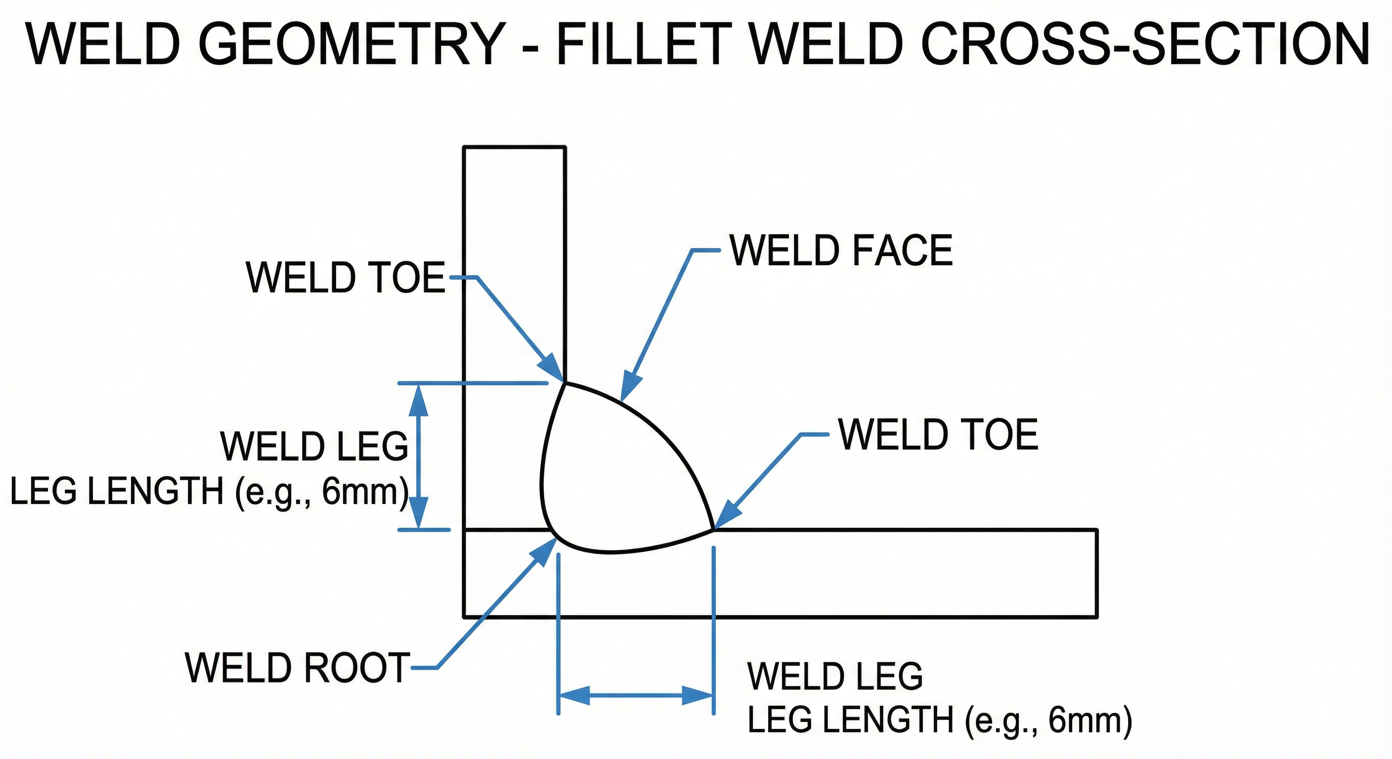
Weld anatomy refers to the specific parts that form when two metals fuse together. Think of it as the blueprint of strength, where each component plays a vital role. The toe, face, leg, and root are four fundamental elements. Together, they determine whether a joint will hold under pressure or fail unexpectedly. Knowing these components helps welders, inspectors, and engineers maintain safety standards effectively.
The Four Primary Weld Components
Before diving deeper, let's explore what makes each component unique and important.
Weld Toe
The weld toe is where magic happens at the junction point. It's the boundary between the weld metal and base metal. Picture the edge where two materials meet—that's your toe. This location experiences significant stress concentration during service. Research suggests it's often the first place where cracks begin forming.
Key characteristics of weld toe:
Located at the outer edge of the weld bead
Creates stress concentration factors that affect fatigue life
Highly susceptible to cracking under cyclic loading
Requires careful inspection using advanced NDT methods
Weld Toe Formation Process
The toe forms naturally as the welding arc cools and solidifies. Metallurgically, the fusion line develops where heat affects base metal structure. The heat-affected zone (HAZ) plays a crucial role here. This zone experiences dramatic microstructural changes without actual melting occurring.
Welding parameters directly influence toe geometry and quality. Arc temperature, travel speed, and electrode angle all matter significantly. Higher heat input creates wider HAZ regions and different toe angles. Lower heat input produces sharper toes that concentrate stress more intensely.
The fusion line develops gradually as molten metal contacts base metal edges. This interaction creates metallurgical bonding between materials. Without proper fusion at the toe, incomplete joint strength results inevitably.
Weld Toe Characteristics & Dimensions
Toe angle specifications vary by application and industry standards. AWS standards typically specify angles between 20-45 degrees. ISO standards may differ slightly in preferred toe geometry requirements. Radius requirements depend on the specific application and material type involved.
Surface finish expectations at the toe remain critical for performance. Smooth transitions reduce stress concentration dramatically compared to sharp angles. The toe radius directly affects fatigue crack initiation resistance significantly.
Weld Toe Defects & Failure Points
Toe cracking represents the most serious defect at this location. Hydrogen-assisted cracking often initiates from sharp toe angles. Prevention involves controlling heat input and preheat temperatures carefully. Stress relieving after welding reduces cracking tendency significantly.
Undercut defects appear as grooves along the toe line. These are caused by excessive arc energy or improper travel angle. Undercuts concentrate stress, reducing fatigue life considerably. Remediation requires grinding away affected areas and re-welding properly.
Incomplete fusion at the toe junction indicates poor material bonding. This defect allows cracks to propagate more easily during service. Causes include low heat input or contaminated base metal surfaces. Prevention requires maintaining proper arc temperature and cleanliness.
Porosity formation near toe regions traps gases in solidified metal. These voids create stress concentration points that initiate cracks. Research suggests excessive travel speed increases porosity formation tendency. Proper shielding gas selection and flow rate prevent porosity effectively.
Remediation techniques vary based on defect severity and location. Minor undercuts need local grinding and inspection. Severe defects typically require complete weld removal and rework procedures.
Weld Toe Significance in Stress Concentration
The stress concentration factor (Kt) at toe regions significantly exceeds base metal levels. Sharp toes create Kt values reaching 3-4 times normal stress. This amplification means stresses concentrate intensely at the toe. Smooth, well-designed toes reduce Kt values to approximately 1.5-2.0 levels.
Fatigue performance correlates directly with toe quality and geometry. Research suggests toe condition affects fatigue life more than any other factor. Sharp toe angles reduce fatigue strength by 40-50 percent. Properly finished toes with generous radii improve fatigue resistance substantially.
Service life implications become clear when examining toe failure rates. Many bridge and pipeline failures originate from toe cracks. Pressure vessel failures often trace back to inadequate toe geometry. Learning from these failures has improved modern welding standards significantly.
Weld Face
The weld face represents the visible surface you see on finished welds. It''s the exposed bead area on the side where welding occurred. This component affects both appearance and performance characteristics. Think of it as the "first impression" of weld quality that inspectors evaluate immediately.
What defines a quality weld face:
Smooth, uniform ripple patterns across the bead
Proper reinforcement height for the application
Clean surface without excessive spatter or oxidation
Consistent width matching specification requirements
Weld Face Formation & Appearance
The face develops as molten metal deposits and cools on the joint. The deposition process creates characteristic ripple patterns. These ripples form from the arc's oscillating motion during welding. Stronger arcs produce deeper, more pronounced ripple patterns.
Ripple formation mechanisms depend on arc energy and travel speed. Higher travel speeds create tighter ripple spacing. Lower speeds result in wider, deeper ripple formations. Electrode diameter influences ripple characteristics significantly as well.
Welding technique dramatically impacts face appearance and quality. Proper angle and arc length produce consistent, uniform ripples. Poor technique creates irregular patterns and surface defects. Skilled welders maintain consistent travel speed and arc conditions throughout.
Bead profile variations include convex, flat, and concave shapes. Convex faces have reinforcement rising above the base metal level. Flat faces align with the base metal surface smoothly. Concave faces dip below the base metal level, creating weak areas. Different applications require different profile types for optimal performance.
Weld Face Geometry & Dimensions
Face width and reinforcement height follow strict standard requirements. AWS specifications typically limit reinforcement to 1/8 inch maximum. ISO standards may specify different reinforcement values. Excessive reinforcement wastes material and creates unnecessary stress concentration.
Flatness versus convexity requirements depend on application type. Structural welds typically allow moderate convexity for strength. Pipe welds often require nearly flat faces for flow. Pressure vessel applications mandate specific reinforcement ranges. Meeting these requirements ensures joint reliability and code compliance.
Ripple spacing and uniformity standards reflect weld quality directly. Uniform ripples indicate consistent arc conditions and travel speed. Irregular spacing suggests technique problems or equipment instability. Standard ripple spacing typically ranges from 1/8 to 1/4 inch apart.
AWS and ISO specification comparisons reveal slight regional differences. AWS D1.1 may allow slightly more reinforcement than ISO standards. Both systems prioritize consistency and defect-free surfaces. Inspectors must understand applicable standards for their specific application.
Weld Face Defects & Quality Issues
Excessive reinforcement increases material cost unnecessarily. It also creates stress concentration zones at toe locations. Over-reinforced welds require additional finishing work and expense. Prevention involves controlling arc parameters and travel speed consistently.
Spatter formation occurs when molten metal particles scatter around. This reduces visual quality and suggests unstable arc conditions. Excessive spatter indicates potential internal defects requiring investigation. Prevention involves proper shielding gas selection and flow rates.
Cold lap conditions appear when weld metal doesn't fuse properly. The new metal simply sits atop the previous layer. This defect significantly reduces joint strength and fatigue resistance. Causes include low heat input or poor cleaning between passes.
Surface oxidation and discoloration appear on stainless and aluminum welds. These indicate improper shielding or contaminated atmosphere conditions. While cosmetic initially, oxidation can accelerate corrosion problems. Proper shielding and post-weld cleaning prevent discoloration effectively.
Remediation approaches vary based on defect severity and location. Minor spatter requires wire brushing and visual re-inspection. Laps and cold fusion typically demand grinding and re-welding. Severe defects may require complete weld removal and restart.
Weld Face Impact on Performance
Fatigue performance relationships show direct correlation with face quality. Smooth, well-finished faces improve fatigue life significantly. Poor faces with defects reduce fatigue strength considerably. Research suggests face condition affects fatigue life 20-30 percent.
Corrosion resistance implications become apparent over service time. Clean, well-finished faces resist corrosion better than rough ones. Surface defects trap moisture and corrosive agents effectively. Stainless steel welds especially benefit from proper face finishing.
Stress distribution across the face influences overall joint behavior. Uniform reinforcement distributes stress more evenly than irregular faces. Excessive reinforcement creates stress concentration at toe regions. Proper face geometry ensures balanced stress distribution throughout.
Influence on subsequent welding passes matters in multi-pass applications. A well-prepared previous face promotes better bonding for new passes. Poor faces with laps or irregularities inhibit fusion. Clean faces between passes ensure consistent quality improvement.
Comparison of quality versus poor face outcomes tells an interesting story. Quality faces show smooth failure patterns during destructive testing. Poor faces reveal premature failures, cracks, and separation. This difference underscores the importance of face quality maintenance.
Weld Leg
Weld legs are specific to fillet welds found in corners and T-joints. Each leg represents one side of the triangular fillet cross-section. Equal legs mean both sides measure the same length. Unequal legs allow engineers to adjust strength distribution as needed. 
Understanding leg dimensions:
Measured from the root to the toe of each leg
Directly determines the weld's throat area and strength
Sized according to AWS, ISO, and EN standards
Must meet minimum requirements based on base metal thickness
Weld Leg Geometry & Sizing
Leg length definitions distinguish between equal and unequal legs clearly. Equal legs measure the same on both sides of the triangle. Unequal legs allow engineers to proportion strength as needed. Size notation uses fractions like 1/4" or 5/16" for example.
Size notation systems standardize leg dimension communication across industries. A 1/4" fillet weld means 1/4" legs on both sides. This straightforward system simplifies specification and verification. Understanding notation prevents costly miscommunication on job sites.
The relationship between leg size and joint strength is proportional. Doubling leg size quadruples the throat area and strength. Conversely, undersized legs create dangerously weak joints. Proper sizing ensures adequate strength without unnecessary material waste.
Standard sizing across AWS, ISO, and EN codes shows variations. AWS D1.1 typically specifies minimum legs based on base metal thickness. ISO standards may differ slightly in their minimum requirements. EN codes provide European standards with comparable specifications.
Weld Leg Formation During Fillet Welding
Deposition geometry in T-joint applications follows specific techniques. The welder deposits metal into the corner, building up both legs. Arc positioning determines how metal distributes between the legs. Proper positioning ensures equal leg development on both sides.
The role of gun angle and arc manipulation proves critical. A 45-degree angle typically produces equal legs effectively. Angling the gun toward one leg creates unequal legs intentionally. Arc movement controls where molten metal flows during deposition.
Travel speed and amperage impacts leg consistency across weld length. Consistent travel speed produces uniform leg sizing throughout. Variable speed creates irregular legs requiring rework. Higher amperage produces larger legs but risks excessive reinforcement.
Multiple-pass fillet weld leg development follows sequential layering patterns. First passes establish leg foundation and root fusion. Subsequent passes build up leg size gradually. Final passes produce finished surface and specified leg dimensions.
Factors affecting leg formation:
Electrode diameter and type selection
Shielding gas composition and flow rate
Welder skill and technique consistency
Base metal surface preparation quality
Weld Leg Defects & Undercut Issues
Undercut at weld legs appears as groove erosion along leg edges. High arc energy causes base metal erosion creating these grooves. Prevention involves controlling amperage within recommended ranges. Proper arc length and travel speed also prevent undercut formation effectively.
Incomplete fusion along leg surfaces indicates poor weld metal bonding. This defect reduces joint strength significantly and allows crack propagation. Causes include low heat input or contaminated base metal surfaces. Prevention requires maintaining proper arc temperature and thorough cleaning.
Lamellar tearing in thick weld legs develops through-thickness. This defect occurs in highly restrained joints with thick materials. Hydrogen-assisted mechanisms drive lamellar cracking development. Preheat and stress relief post-weld reduce lamellar cracking tendency.
Leg size inconsistency across weld length signals technique or equipment problems. Variable leg sizing creates weak spots in the joint. Inconsistency suggests unstable arc conditions or variable travel speed. Maintaining consistent technique prevents this common defect.
Minimum leg requirements for strength come from industry standards directly. Undersized legs cannot carry design loads safely. Proper sizing ensures adequate strength throughout service life. Verification through measurement confirms leg dimensions meet specifications.
Weld Leg Measurement & Verification
Fillet weld gages and measurement techniques provide direct assessment methods. Specialized gages measure leg dimensions quickly and accurately. These tools clamp directly onto the weld, reading leg size. Regular calibration ensures measurement accuracy and reliability.
Cross-section visual inspection reveals actual leg dimensions internally. Cutting samples perpendicular to the weld shows true profile. Microscopic examination confirms leg geometry and fusion quality. This destructive testing method provides definitive verification.
Destructive testing for leg verification includes bend and tensile testing. These tests confirm joint strength meets or exceeds standards. Bend tests specifically reveal fusion quality between legs and base metal. Failure modes indicate whether defects contributed to weakness.
Weld Leg Contribution to Joint Strength
Throat area versus leg size calculation determines actual joint strength. Throat area equals leg size multiplied by 0.707 mathematically. This relationship shows why precise leg sizing matters critically. Larger throat areas provide proportionally greater load capacity.
Strength rating by leg dimension follows code-specified formulas exactly. Each leg size corresponds to specific allowable load values. Engineers use these ratings to select proper weld sizes. Undersized welds cannot carry design loads creating failure risk.
Minimum leg requirements by code ensure adequate safety factors. Standards require legs sized for 1.5 to 2.0 safety factors. This built-in safety margin protects against overloads and uncertainties. Proper sizing maintains this safety factor throughout service.
Oversizing implications increase material costs and welding time needlessly. Excessive leg size wastes filler metal and creates extra heat. This additional heat can cause distortion and residual stress. Cost-benefit analysis typically favors right-sizing over oversizing.
Weld Root
The weld root is perhaps the most critical yet hidden component. It's the deepest point where fusion occurs in groove welds. Many failures originate here because root defects go undetected easily. Complete penetration at the root ensures maximum joint strength and reliability.
Why root quality matters most:
First point where cracks typically initiate during service
Requires specialized inspection techniques like radiography
Incomplete penetration creates stress concentration zones
Poor root condition significantly reduces service life expectancy
Weld Root Formation & Root Penetration
Root penetration defines how deep the weld melts into the joint. Complete penetration means the weld reaches fully across the joint. This depth directly determines actual joint strength and reliability. Research suggests complete penetration improves fatigue resistance significantly.
Root penetration definition and measurement uses specific technical standards. Penetration is measured from the root surface to deepest fusion point. Standards specify minimum penetration values for various applications. Achieving these minimums ensures adequate joint performance.
Root fusion mechanisms in groove welds involve complex metallurgical processes. The arc melts both base metal edges creating a molten pool. This molten material solidifies forming a permanent bond. Proper heat and cooling control ensures quality fusion throughout.
Single-pass versus multi-pass root formation follows different procedures. Single-pass roots must achieve complete penetration in one pass. Multi-pass roots establish initial fusion with subsequent passes adding strength. Each approach requires specific parameter adjustment and technique.
Impact of root opening, geometry, and parameters on penetration proves significant. Larger root openings allow deeper penetration with same parameters. Root face dimensions influence heat distribution and melting patterns. Welding parameters directly control how deep fusion penetrates.
Complete versus incomplete penetration scenarios show dramatically different performance. Complete penetration provides maximum strength and fatigue resistance. Incomplete penetration creates stress concentration zones promoting crack initiation. Service failures often trace back to incomplete root penetration problems.
Weld Root Geometry & Specifications
Root opening (gap) specifications standardize joint preparation geometry. Typical root openings range from 1/8" to 3/16" depending on parameters. Larger gaps allow deeper penetration but require more skill. AWS standards specify opening ranges for various materials and thicknesses.
Root face dimensions and purposes define the land area. Root face provides a backing surface during root pass welding. Proper face dimensions ensure adequate backbead formation without burnthrough. Typically, root faces measure 1/8" to 3/16" width.
Root reinforcement and back-bead characteristics affect final weld strength. Reinforcement in groove welds provides additional metal in the root region. Back-beads on double-sided welds indicate complete penetration visually. Excessive reinforcement creates stress concentration requiring grinding.
Backhand versus forehand root welding effects differ significantly. Backhand welding (pushing) produces narrower, deeper beads. Forehand welding (pulling) creates wider, flatter beads. Backhand typically achieves better penetration with comparable skill levels.
Standard root geometry across codes provides consistent guidance. AWS D1.1, ISO 5817, and EN standards all specify similar requirements. Minor variations exist but principles remain consistent globally. Understanding applicable standards prevents costly rework on projects.
Weld Root Defects & Failure Modes
Lack of fusion at root (cold root conditions) prevents material bonding. This defect appears when the arc doesn't provide sufficient heat. Cold roots allow cracks to propagate through the weak bond. Prevention requires maintaining proper arc length and amperage.
Incomplete penetration represents perhaps the most dangerous root defect. This condition means the weld doesn't reach completely across the joint. The unbonded material creates internal discontinuities and stress concentration. Many catastrophic failures originate from undetected incomplete penetration.
Root porosity and its implications reduce structural integrity significantly. Porosity creates voids within the solidified metal. These voids concentrate stress and initiate fatigue cracks. Causes include excessive moisture in shielding gas or inadequate deoxidizers.
Root cracking (hydrogen-assisted cracking) develops during cooling. Hydrogen trapped during welding promotes cracking in susceptible materials. Thick sections and high restraint increase cracking tendency significantly. Preheat and stress relief reduce this serious defect effectively.
Root concavity and convexity issues affect joint strength differently. Concave roots have thin areas that weaken the joint. Convex roots provide extra metal, improving strength moderately. Standards typically specify slight convexity as acceptable.
Weld Root Quality Impact on Service Performance
Root defect relationship to service failures shows clear correlation. Many documented failures trace back to root defects. Research suggests 60-70% of weld failures originate at root regions. This alarming statistic emphasizes root quality importance continuously.
Fatigue crack initiation at root discontinuities occurs predictably. Sharp defect edges concentrate stress amplifying cyclic loading effects. Cracks propagate through the weak root region eventually causing failure. Well-fused roots resist fatigue initiation dramatically better.
Root defects in high-pressure vessels create catastrophic failure risks. Pressure amplifies stresses concentrating at defect locations intensely. Even minor root porosity can trigger rapid failures. Consequently, pressure vessel codes mandate stringent root requirements.
Root condition in pipeline and structural applications affects long-term reliability. Pipelines experience cyclic loading from pressure fluctuations. Defective roots fail prematurely under these demanding conditions. Structural failures similarly often trace to root quality problems.
Cost of root repair versus complete re-weld involves economic decisions. Minor root defects may allow targeted grinding and repair. Extensive defects often require complete weld removal and restart. Prevention through proper technique proves far more cost-effective ultimately.
Conclusion
Welding components are the building blocks of structural integrity and safety. Understanding each component's role prevents costly failures and accidents. When you grasp how these parts work together, quality improves dramatically. Better welds mean safer structures, longer service life, and fewer emergencies. Inspectors catch defects earlier when they understand anatomy thoroughly. Welders make better decisions knowing component importance directly. Whether you're building bridges, pipelines, or pressure vessels, this knowledge matters.